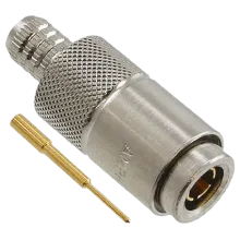
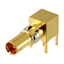
1.0/2.3 series (often called DIN 1.0/2.3) are either a 50 Ω connector with a 10 GHz cutoff, or a 75 Ω connector with a 4 GHz cutoff featuring a smaller centre conductor, both variations are covered by the DIN 47297 standard. 1.0/2.3 RF connectors are characterised by high mechanical and electrical stability.
The connectors are designed for high density applications, offering a 40% size reduction to the similar 1.6/5.6 RF connector. In addition to the two types, there are several subtypes featuring different coupling mechanisms, listed below. It should be noted however that not all manufacturers produce all subtypes.
- Type A - Screw-on mechanism with coupling nut
- Type C - Slide-on coupling with centering sleeve
- Type E - Snap-on coupling with retention clip
- Type F - Quick lock
History
The 1.0/2.3 connector series was introduced to the European telecommunications market in the 1990s under the DIN 47297 standard to support an increasing demand for high density applications unsuitable for older connectors like TNC.
Applications
The compact design permits dense connector packing and makes them ideal solutions to applications where space limitation is a factor. As a high frequency connector the connector is often used in dense microwave band applications requiring high data rates, such as in digital broadcast and CATV distribution, particularly with the development of ganged backplane systems.
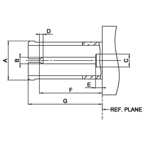
Male Dimensions

| Legend | Min | Max |
|---|---|---|
|
A (Ø)
|
||
|
B (Ø)
|
0.4750
|
0.5200
|
|
C (Ø)
|
1.0000
|
1.0000
|
|
D
|
0.4000
|
|
|
E
|
1.1500
|
|
|
F
|
5.5000
|
|
|
G
|
5.4000
|
5.5700
|
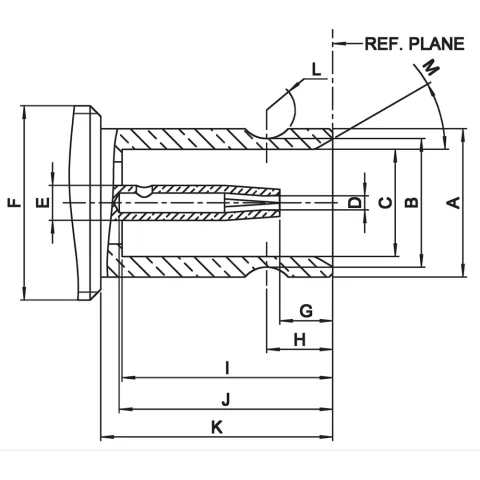
Female Dimensions

| Legend | Min | Max |
|---|---|---|
|
A (Ø)
|
4.0300
|
4.1500
|
|
B (Ø)
|
3.5250
|
3.6000
|
|
C (Ø)
|
3.0000
|
3.0600
|
|
D (Ø)
|
||
|
E (Ø)
|
1.0000
|
1.0000
|
|
F (Ø)
|
||
|
G
|
1.1500
|
1.7500
|
|
H
|
1.8000
|
1.9000
|
|
I
|
5.8000
|
5.9000
|
|
J
|
5.5000
|
|
|
K
|
6.4000
|
6.5000
|
|
L (r)
|
0.8000
|
0.8000
|
|
M (°)
|
28.0000
|
32.0000
|

