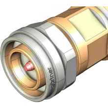
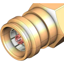
The 4.3-10 RF connector has been designed as a compact and low PIM replacement to traditional 7/16 DIN connectors, and an iterative improvement over even the more recently developed 4.1/9.5 "Mini-DIN" connector.
The 4.3-10 connector features a screw-on, low torque coupling system, with a separation of the electrical from the mechanical plane ensuring performance does not vary with torquing.
The series can be supplied as IP67 / IP68 certified from leading manufacturers and are an ideal drop-in replacement for broadcast applications utilising 7/16 DIN connectors. Their popularity has been fuelled by the increasing use of multiport and MIMO cellular base station antennas, with their 40% smaller and 60% lighter form factor permitting higher density packing of connectors at the base of each antenna.
4.3-10 connectors are low PIM by design, described as "virtually PIM free", making them ideal for 5G mobile communication systems and wireless applications. While the IEC 61169-54 standard states cutoff frequency of 6 GHz, many vendors offer connectors up to 12 and 13 GHz.
History
As LTE threatened to push mobile broadband data rates past the 100 Mbps barrier, leading vendors recognised the need to develop a new RF connector that met the demand for low PIM, as the higher data rates exposed vulnerabilities in traditional transmission sites. PIM threatened to impose an upper limit on modulation schemes, and thus achievable data rates, by deteriorating signal fidelity.
The increasing need for multiport and MIMO antenna systems to facilitate such data rates also meant size and weight became a serious design concern. Beginning 2012, leading vendors (SPINNER, Telegärtner, Rosenberger, and Huber+Suhner) collaborated on the design and developed the new IEC 61169-54 RF connector standard which was released in 2016.
Applications
4.3-10 connectors are low PIM by design, described as "virtually PIM free", making them ideal for mobile communication systems and wireless applications. These connectors are able to match the performance and mechanical robustness of a 7/16 connector in a 40% smaller footprint, and as such are suitable for a range of broadcast applications.
In addition to being 40% smaller and 60% lighter, the low-torque mating design allows antenna designers to use a lighter mounting frame, further reducing antenna size and weight. The connector also finds its use as a replacement for N connectors in cellular DAS systems requiring PIM certification.
Variations
IEC 61169-54 defines three variations of the 4.3-10 male interface; screw-on, hand-screw, and quick-lock, with all three mating to a single universal female interface. Due to the design differences all three coupling mechanisms have their advantages and disadvantages and therefore all of them have their place:
- Screw type connectors do not allow a free rotation of the cable but are, due to their higher coupling torque of 5 Nm, very insensitive against opening by torque forces on the cable.
- Generally, the hand-screw and push-pull type connectors are designed to allow rotation of the cable. However, a hand screw coupling mechanism can be opened by applying a pulling and/or bending force together with a torque force. While a push-pull mechanism by design is immune against any undesired opening by torque forces, even in combination with bending and/or pulling forces.
- The mechanical stability of a mated connector pair is at the maximum for screw type couplings. And even though the spring loaded outer conductor contact allows stable PIM values even for push-pull or hand screw connectors and under dynamic conditions, the PIM risk is minimised for screw type connectors.
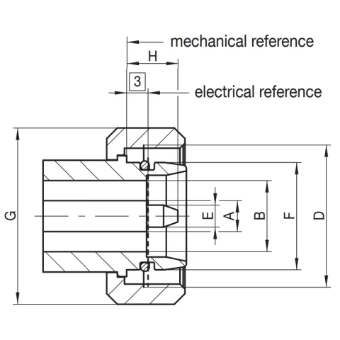
Male Dimensions (courtesy Rosenberger)

| Legend | Min | Max |
|---|---|---|
|
A (nom.)
|
4.3500
|
|
|
B (nom.)
|
10.0000
|
|
|
C
|
||
|
D (M20 x 1)
|
||
|
E
|
3.0700
|
3.1300
|
|
F
|
15.0700
|
|
|
G SW 22
|
||
|
H
|
8.0000
|
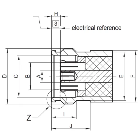
Female Dimensions

| Legend | Min | Max |
|---|---|---|
|
A (nom.)
|
4.1300
|
|
|
B
|
9.8000
|
10.2000
|
|
C
|
15.1300
|
15.1900
|
|
D (M20 x 1)
|
||
|
E
|
17.4500
|
17.5500
|
|
F
|
18.6000
|
|
|
G
|
||
|
H
|
3.1000
|
3.5000
|
|
I
|
8.7000
|
9.0000
|
|
J
|
13.9000
|
14.1000
|
|
K
|
17.4000
|
17.5000
|
|
L
|
18.4400
|
18.5000
|
|
M
|
1.4400
|
1.5000
|
|
N
|
1.7000
|
1.9000
|

