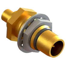
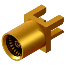
The Blind-Mate A (BMA) RF connector are a slide-on/push-on series developed for interconnecting microwave modules, using direct mount or floating rear mount. The floating variation of the female connector is employed to provide tolerance against misalignment during mating, and has also made the series popular in high vibration applications. The connector series is commonly referred to as OSP, despite the official military standard designation of BMA. The connector design has been standardised through MIL-STD-348B and IEC 61169-33.
Images and data courtesy of SV Microwave.
History
The connector was developed in the 1980's and originally designated as the OSP™ connector by M/A-Com.
Applications
Supporting applications up to 22 GHz and with a design capable of handling in excess of 5,000 mating cycles, BMA connectors are used for interconnecting microwave modules, drawers, and racks in high frequency systems that do not allow longer system down time. BMA push-on connectors allow replacement of faulty high power microwave modules within seconds. The series is generally considered obsolete as it has been replaced by improved blind-mate SBX, SBY, SMP, and Mini-SMP connectors.
Variations
Female BMA (OSP) connectors can be fixed or floating. Floating connectors are used to tolerate axial or radial misalignment whereby the spring mechanism separates the connector interface from the flange housing and allows floating for blind mating purposes.
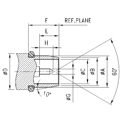
Male Dimensions

| Legend | Min | Max |
|---|---|---|
|
A
|
5.3100
|
5.3600
|
|
B
|
4.9000
|
|
|
C
|
4.0900
|
|
|
D
|
7.6200
|
|
|
E
|
3.2500
|
|
|
F
|
5.0300
|
|
|
G
|
0.9000
|
|
|
H
|
2.2900
|
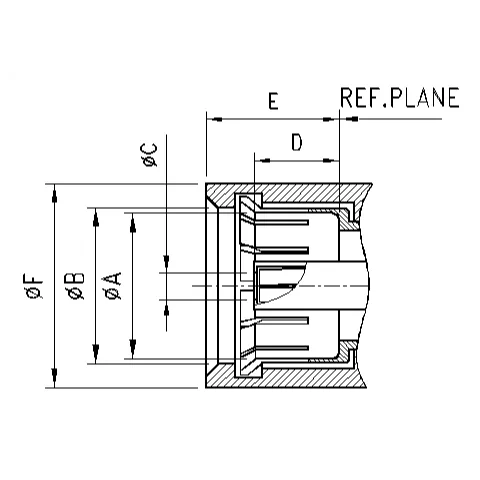
Female Dimensions

| Legend | Min | Max |
|---|---|---|
|
A
|
5.0800
|
|
|
B
|
5.7200
|
|
|
C
|
||
|
D
|
3.2300
|
|
|
E
|
5.0300
|
|
|
F
|
7.3700
|

