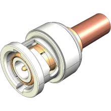
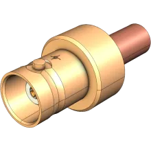
BNC "Bayonet Neill–Concelman" are a two-stud bayonet-style connector designed for quick mating. BNC connectors are one of the worlds most popular type of RF connector. Originally designed for early military communications, BNC connectors are now commonly used in UHF, radio, electronic equipment, and broadcast up to 4 GHz. Above 4 GHz, BNC slots begin radiating resulting in a hard limit to the series operating frequency range. Characteristic impedance is 50 Ω, although 75 Ω designs supporting up to 2 GHz are also commonplace.
History
As the name suggests, the connector was designed collaboratively by Paul Neill from Bell Labs, and Carl Concelman from Amphenol. The development however was based on an earlier design by Octavio M. Salati who filed for a design patent in 1945, with patent #2,540,012 being granted in 1951. Accordingly the BNC connector is considered an iterative improvement of Octavio's design, rather than an entirely new invention.
Applications
50 Ω impedance BNC connectors are heavily utilised in a range of telecommunications applications such as UHF radio, data communications, SCADA, and formed the basis of early 10BASE2 computer networks. 75 Ω BNC connectors are used for a wide range of analogue and digital video transmission applications including, MATV building distribution, CCTV, and CATV.
Variations
In addition to the 75 Ω design, BNC connectors can be reverse-polarised, swapping the male and female centre conductors to prevent accidental mating of incompatible technologies. Many manufacturers have also released proprietary variations often considered as entirely new connector series. These include "High Density" HD-BNC, a 75 Ω connector with a 25% smaller footprint, and Mini-BNC, a miniaturised 75 Ω connector 40% smaller than conventional BNC connectors.
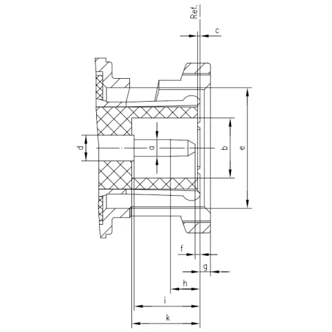
Male Dimensions (Courtesy Telegärtner)

| Legend | Min | Max |
|---|---|---|
|
A
|
1.3200
|
1.3700
|
|
B
|
4.8300
|
|
|
C
|
0.1500
|
|
|
D
|
2.0600
|
2.2100
|
|
E
|
9.7800
|
9.9100
|
|
F
|
0.0800
|
1.0200
|
|
G
|
1.4400
|
1.4400
|
|
H
|
1.9600
|
3.0500
|
|
I
|
5.3300
|
|
|
K
|
5.2800
|
5.7900
|
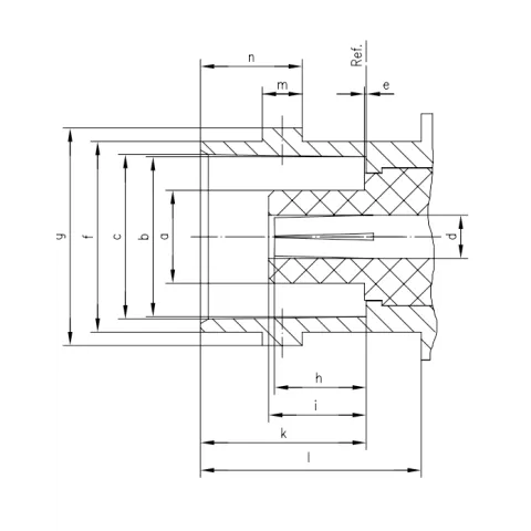
Female Dimensions

| Legend | Min | Max |
|---|---|---|
|
A
|
4.7200
|
|
|
B
|
8.1000
|
8.1500
|
|
C
|
8.3100
|
8.4600
|
|
D
|
1.8800
|
2.2900
|
|
E
|
0.1500
|
|
|
F
|
9.6000
|
9.7000
|
|
G
|
10.9700
|
11.0700
|
|
H
|
4.5500
|
5.2300
|
|
I
|
5.2800
|
|
|
K
|
8.3100
|
8.5100
|
|
L
|
10.5200
|
|
|
M
|
1.9100
|
2.0500
|
|
N
|
5.1800
|
5.2800
|

