The following article serves to build an understanding about the antenna parameter known as Inter-Port Isolation. The parameter, sometimes referred to as Port-to-Port Isolation, is a simple metric that allows RF engineers to understand how well any two signals on a multiport or MIMO antenna are isolated from each other. Understanding the parameter is particularly important in the design of cellular and multipoint base stations as selecting antennas with high isolation reduces the complexity and level of filtering required.
Achieving high inter-port isolation follows the same principles as conventional antenna isolation. Coupling reduces the further internal antenna elements are separated, by placing insulating or absorbing materials between elements, and when of orthogonal polarities. One consideration is that antenna elements are only efficient radiators at their tuned frequency range and so design engineers often factor in this natural bandpass filter-like behaviour.
The remaining means of improving isolation are dependent on the antenna type. Large antennas can integrate passive components such as bandpass, notch, helical, and ceramic filters. Microstrip and PCB based antennas can use Electromagnetic Band-Gap (EBG), Defected Ground Structure (DGS), and other decoupling structures to improve isolation.
Definition of Inter-Port Isolation
Ratio in dB of the power level applied to one port of a multi-port antenna to the power level received in any other port of the same antenna as a function of frequency.
Specification Definition
When disclosing inter-port isolation on test reports and datasheets, R-Spectrum follow the BASTA reporting recommendations. Powertec have deferred to ETSI recommendations for the use of the term Inter-Port Isolation over Port-to-Port Isolation referred to by BASTA.
- An absolute parameter.
- Specified as a minimum value in dB measure between a pair of ports.
- Coupling between individual ports is best described in terms of “S parameters”. For example, the magnitude in dB of the coupling from port 1 to port 2 is signified by S12.
- For passive devices, such as antennas, coupling is reciprocal, that is, S12 = S21.
- Specification shall reference the full frequency range, full electrical downtilt range, and associated ports of the antenna unless specifically detailed otherwise (example: 1695 to 2180 MHz; 0°-10°; +45 and -45 ports).
- Since this specification is for a specific pair of ports, they must be identified on the antenna and referenced in the same way in the specification.
Example Specification
For two port antennas a single datasheet entry will suffice. The below specification represents a single-band, single beam, dual-polarised ±45° antenna (two ports).
Inter-Port Isolation: > 22 dB
For multiport antennas a table is generally the most effective way of conveying values. The below table represents a tri-band, dual-beam (30° squint), dual-polarised ±45° antenna (12 ports).
| Inter-Port Isolation | 1695 to 1880 MHz | 1850 to 1990 MHz | 1920 to 2200 MHz |
|---|---|---|---|
| Beam +30° +45 to Beam -30° -45 | > 30 dB | > 30 dB | > 30 dB |
| Beam +30° +45 to Beam -30° +45 | > 20 dB | > 20 dB | > 18 dB |
| Beam +30° -45 to Beam -30° -45 | > 20 dB | > 20 dB | > 18 dB |
Testing & Reporting
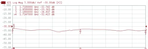
Testing for inter-port isolation is performed in the same manner as many other S-parameter tests, using a two port vector network analyser (VNA) or similar instrument.
An example measurement between two antenna ports is shown below.

References
- NGMN, "Recommendations on Base Station Antenna Standards", NGMN Alliance, N-P-BASTA v11.1, Mar. 2019.
- FEKO, Whitepaper - Design and Optimisation of an LTE Mobile Phone Antenna, [Online], Available: http://www.feko.info/applications/white-papers/design-and-optimisation-of-an-lte-mobile-phone-antenna