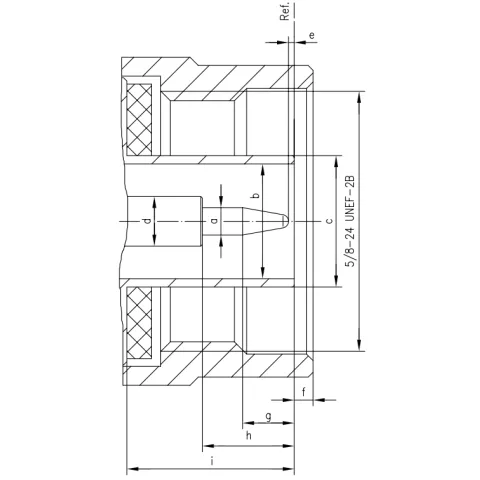
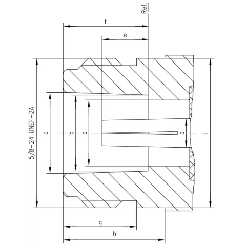
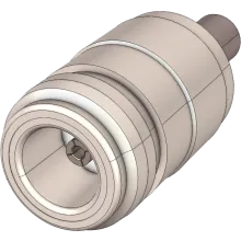
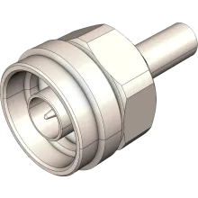
The N connector remains one of the most commonly used RF connector in circulation. N connectors can be found in any telecommunications application from VHF to Sub-6 GHz microwave. Most manufacturers specify an upper operating limit of 3 to 6 GHz, with high quality variants up to 11 GHz
About the N Connector
The "Navy" series connector, also known as Type-N or N-Type, was originally designed for military communications. The N connector remains one of the most commonly used RF connector in circulation. The connector's dimensions are standardised under MIL-STD-348A.
N connectors have a 5/8 - 24 UNEF threaded coupling and are often considered weatherproof for low frequency applications, however lack of internal gaskets make weatherproofing necessary for reliable operation. N connectors have a 50 Ω characteristic impedance, with 75 Ω variations also available with modified contact and dielectric configuration.
Most manufacturers specify an upper operating limit of 3 to 6 GHz, with high quality variants up to 11 GHz, and precision types operating to 18 GHz.
Variations
N connectors are available in General Purpose (the common N connector we use today), a precision type operating to 18 GHz, and a variation governed by MIL-T-81490 termed the EWN connector.
Male Dimensions

| Legend | Min | Max |
|---|---|---|
|
A
|
1.6000
|
1.6760
|
|
B
|
7.0000
|
7.0000
|
|
C
|
8.0270
|
|
|
D
|
3.0400
|
3.0400
|
|
E
|
0.0000
|
1.5700
|
|
F
|
0.4100
|
1.5200
|
|
G
|
2.7900
|
3.5600
|
|
H
|
5.3300
|
|
|
I
|
9.2500
|
Female Dimensions

| Legend | Min | Max |
|---|---|---|
|
A
|
7.0600
|
|
|
B
|
8.0270
|
8.1300
|
|
C
|
8.5300
|
8.7400
|
|
D
|
3.0400
|
3.0400
|
|
E
|
4.7500
|
5.2600
|
|
F
|
9.0500
|
9.1900
|
|
G
|
6.7600
|
|
|
H
|
10.7200
|
|
|
I
|
15.9300
|

