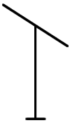
This page acts as a quick reference to IEEE Std 315-1975 for the production of antenna component diagrams, containing the most commonly used RF symbols. It is important to note that this article is not exhaustive and contains only commonly used symbols. Symbol graphics are provided free for use to all Powertec clients.
Antenna Symbols
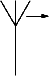
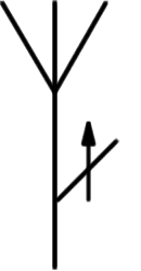
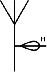
Types of functions may be indicated by words or abbreviations adjacent to the symbol. Qualifying symbols may be added to an antenna symbol indicating properties. If required, the general shape of the main lobes may be shown adjacent to the symbol and notes added to show direction and rate of movement (for example, radar rotation).
General Antenna Symbols
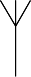
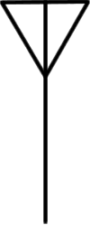
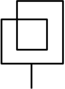
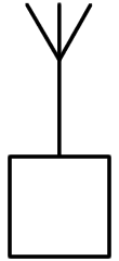
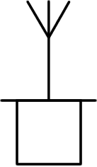
Two general antenna symbols are commonly accepted, and can be used interchangeably. Dipole, Loop, and Counterpoise may be indicated using their respective symbols if desired.
| General | General | Dipole | Loop | Counterpoise (Ground) |
Antenna Qualifying Symbols
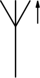
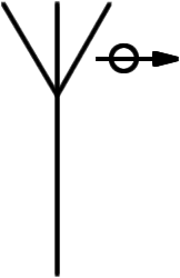
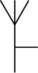
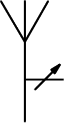
Qualifying symbols can be used to indicate a special property of the antenna to indicate polarisation, direction of radiation, or a particular application. These should only be appended to antenna symbol if essential. Some examples provided below. It is important to again note that these symbols are not exhaustive.
| Horizontal Polarisation | Vertical Polarisation | Circular Polarisation | Radiation Fixed in Azimuth | Radiation Adjustable in Azimuth | Radiation Adjustable in Elevation | Horizontal Polar Diagram |
Example - Radar Antenna
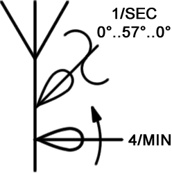
The following denotes a radar antenna rotating four times per minute in azimuth, and reciprocating in elevation 0° to 57° to 0° in one second.
RF Connectors
RF connector genders are designated either Male (Plug) or Female (Jack) based on the physical characteristics of the connector body and centre contact. The following symbols indicate male and female coaxial connectors. It is important to note that the contact symbol is not an arrowhead, it is larger and lines are drawn at a 90 degree angle.
Female - Receptacle/Jack
In identification of the female RF connector, the centre contact consists of a receptacle/socket. Body features a coupling mechanism complementary to the plug.
Male - Plug
In identification of the male RF connector, the centre contact consists of a pin. Body typically features the active part of the coupling mechanism (e.g. coupling nut).
Engaged Connectors
The symbol below represents a male and female coaxial connector when mated.
The symbol below represents the mating of genderless coaxial connectors.
Wireless Link
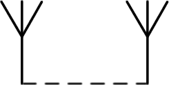
The symbol for a wireless link is represented simply by the display of transmitting and receiving antenna symbols, connected by a Radio Link transmission line symbol, which consists of a series of dashes.
Wireless Stations
The following represent commonly used RF station symbols used on system diagrams, maps, and charts. Other antenna symbols may be used to indicate specific types.
Ground-Based
Symbols in this category are used to represent conventional ground-based transmission stations, such as telecommunications towers, vehicle mounted radio transmitters, aviation beacons, etc.
| General | Portable | Mobile | Direction-finding | Radio Beacon | Controlling | Passive Relay |
Space Station
Symbols in this category are used to represent stations relating to satellite broadcast and earth communications (satellite ground stations, earth terminals, etc).
| General | Active Space Station | Passive Space Station | Earth Station tracking space station |
Waveguides
Commonly used waveguide symbols are found below. Mode of propagation and other special characteristics, including depicting subtypes, may be indicated by the use of qualifying symbols or characters.
| Circular Waveguide | Rectangular Waveguide | Coaxial Waveguide | Flexible Waveguide | Twisted Waveguide | Ridged Waveguide |
Grounding
One of the most common types of surge protection found in RF applications is the gas-discharge tube lightning arrester.

